Hammond X5 Organ Repair and Installing the FlatKeys FK50240 Top Octave Synthesiser Chip PT1

This Hammond X5 came to me with various issues that are common with these old organs and sometimes unless you have a lot of spare time on your hands are not economical to repair. This particular example would probably come under that bracket but me being me I decided that I’d give it a go.

hamond top open big

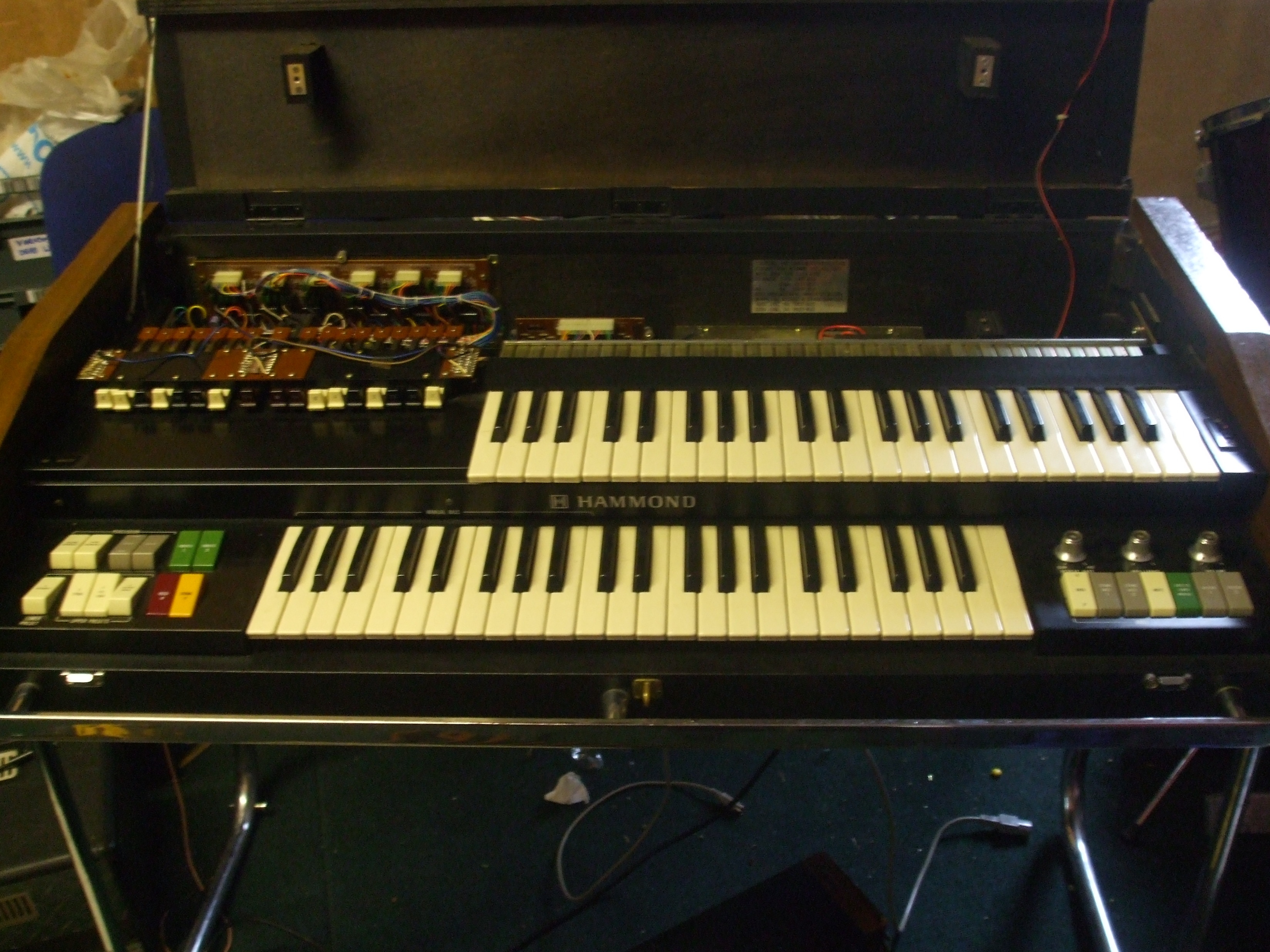
The organ would only make horrible noises when it was dropped off for the repair that was a new issues that wasn’t on the to do list before I  had even started. I sounded all distorted and sometimes would suddenly sound alright for a split second. This beings as it had only just been transported smacked of a bad connection but no amount of wiggling connectors especially the ones from the amp and volume pedal did nothing. So I started tapping on thing to see if I could aggravate the issue and as soon as I tapped on top of the amp that is house in the pedal board assembly in sound would jump back every time I tapped. So out came the pedal board.

hammond pedal board amp side

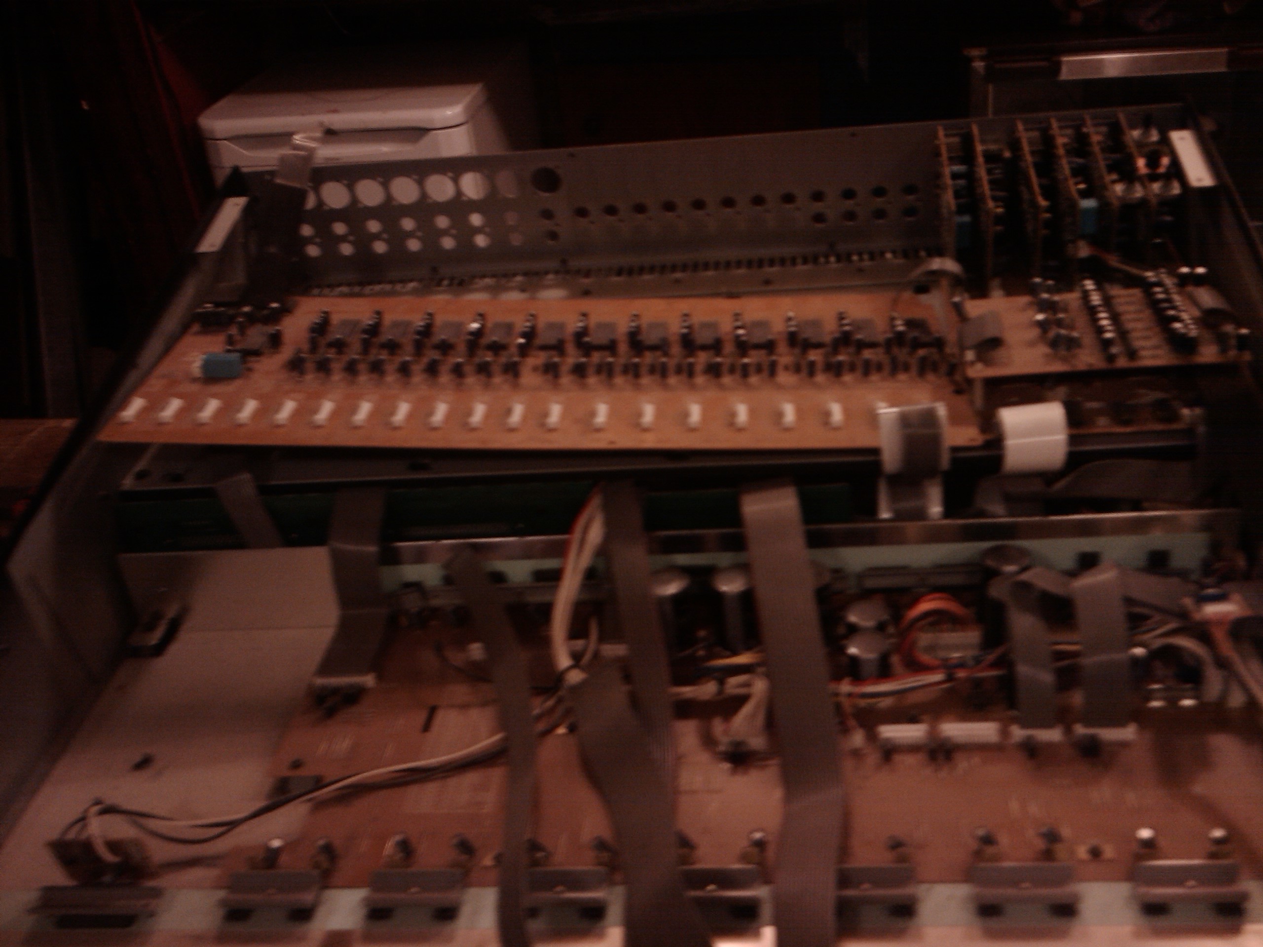
As you can see the pedals are on the left. The volume pedal is in the middle and the silver box to the right is the amplifier (The amplifier is a solid state in the X5.). After opening the amplifier cover I could immediately see that I wasn’t the first person here. Not surprising given the age of the instrument.

hammond x5 amp open

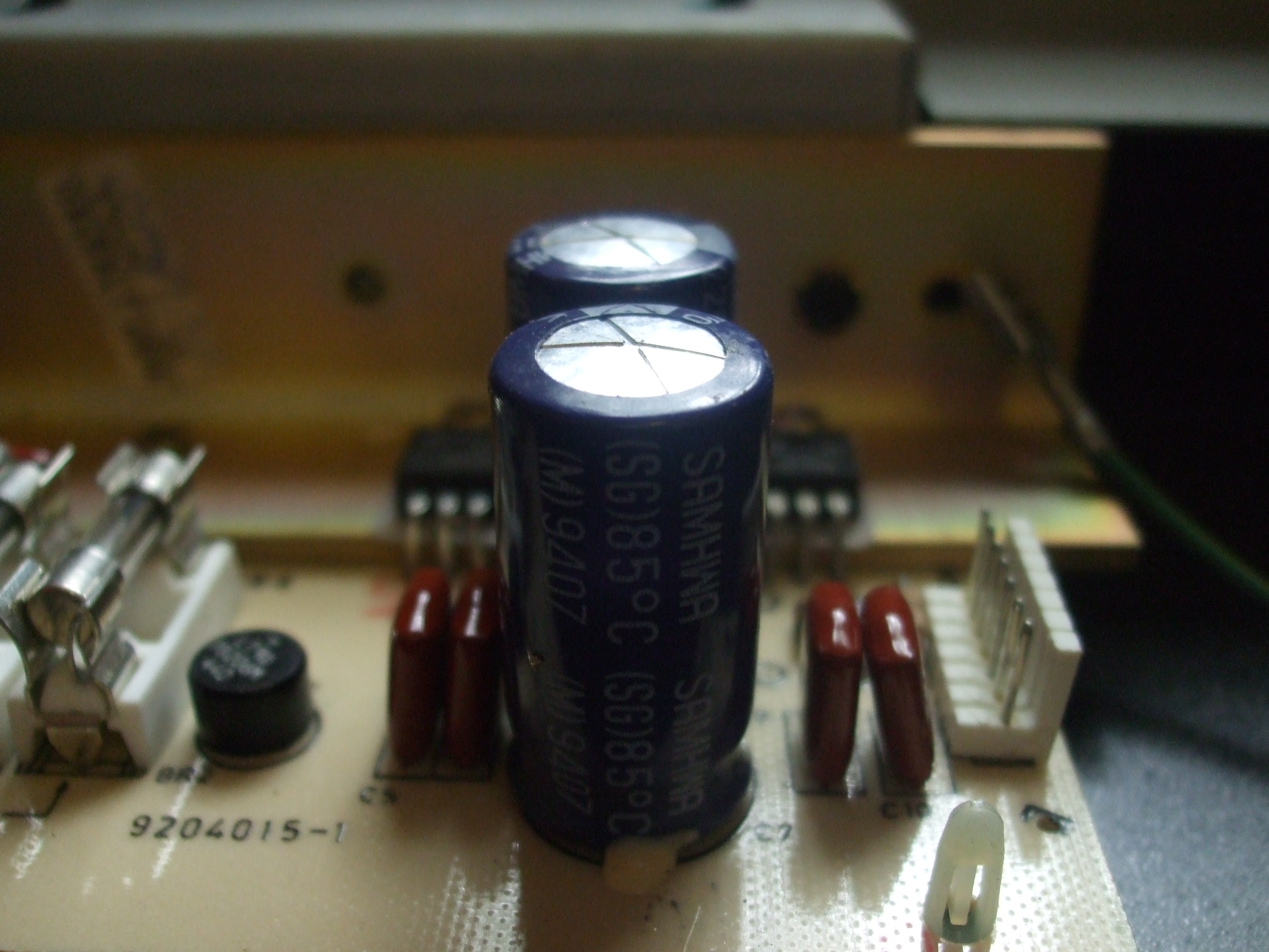
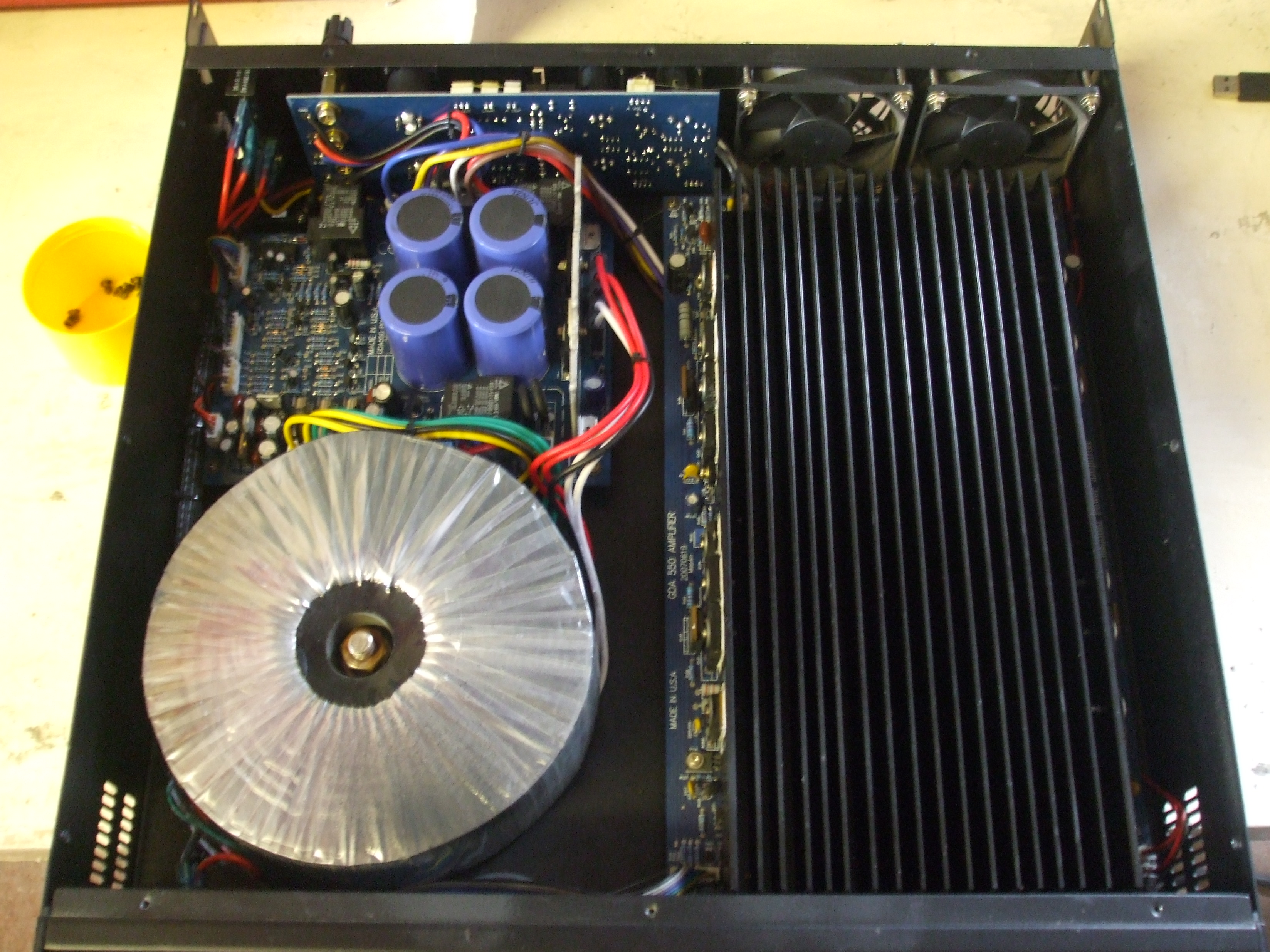
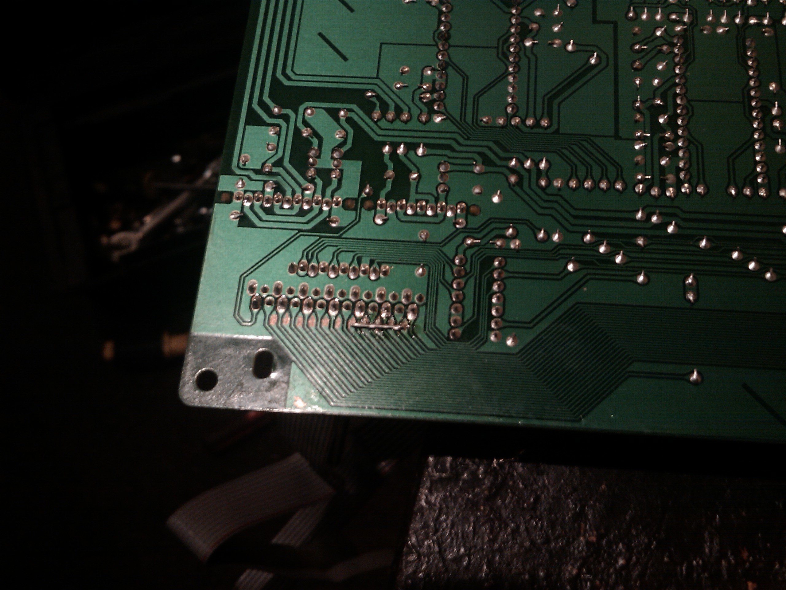
Here you can see the large transformer to the left, the bridge rectifier in the upper middle, large reservoir caps to the upper right and main power amp module with the PCB attached to a heat sink. As the problem was most likely a cold solder joint I started with a quick inspection. There were lots of joints that looked suspect which kind of got me a bit worried about the condition of the rest of the organ.

hammond amp pcb

My plan of attack here was a more of a shotgun approach as every joint looked suspect. I soldered all of the joints and was kind of confident that it would solve the issue and luckily it did. Due to the solder looking bad it will probably stop the organ from developing a problem further down the line. I tested the amp with a 1kHz sine wave and all looked good.

amp sine test

Ignore the tiny bits of distortion and voltage as I’m sure this was done unloaded and was really just to see if the amp was working.

Now with the amp plugged back into the organ the other host of problems became apparent. Here’s the list I wrote down at the time (please note I don’t play organ and some of my terminology make be incorrect).

  • The volume pedal was very twitchy. I put that down to a bad pot, but it wasn’t as you’ll see later.
  • Half the key wouldn’t work
  • Percussion on the pedals made awful noises if and when present
  • There didn’t seem to be and difference in note on the keys that worked
  • Sometimes it would make a god  awful bang.

Now with all that said these were just the ones I wrote down at the time and didn’t really cover anything such as cosmetics or noisy controls but gave me a plan of attack to get the organ somewhat useable first.

My next job was the pedal as it was still exposed and ready to work on, hence why it made the top of the list.

Hammond volume pedal top

Here we can see the pedal without its rubber cover as I was trying to save time getting to the potentiometer to clean it but was slowly beginning to  realise it didn’t have one.

hammond vol pedal back

What the X5 uses is a bulb and an LDR (light dependent resistor) to gauge the position of the pedal by using a slit that has a blocking plate that moves in front of the LDR to adjust the amount of light it sees from the bulb. I pulled out the bulb to make sure it was seated in its holder and this happened.

hammond pedal bulb

Now the bulb didn’t seem too secure, but if the loose wire was the issue then I’m not sure. After re-attaching the wire and a quick once over of all the joints with fresh solder it seemed fine and was working once again. I gave the entire board a quick clean up and made a nice new shroud for the pedal out of card. I think it may also have a part to play as the light was getting in and the bulb was not working. Here is a picture of the old shroud.

pedal board shroud

I didn’t get a pic of the new one, but I’m sure we can all use our imagination and accept that I did an awesome job and it didn’t look like a one year old did it honest.
Anyway I’ll leave this here and come back with a part two as this one is going to be long and me having to remember every detail is also an issue here.
See you later for part two where it all gets a bit mad and I add a bit of a twist provided by FlatKeys.


Studiomaster Diamond pro 8-3 Repair

This desk came to me completely dead no power lights or anything. These desks are pretty simple beasts and there really isn’t much in them to go wrong. With the symptoms I assumed that this was probably a case of a bad connection as they do seem to suffer from the multi-pin leads becoming corroded. On opening the desk I noticed straight away that the power supply output capacitors had bulges in the top.

DSCF0012

This isn’t uncommon in electrical gear of this age as these components have a finite life. I checked the rails going to the channel strips for shorts but all measured well.

I removed the power supply PCB and found this.

DSCF0021

Im not sure if this is factory bodge work or not but all the connections seem to follow the traces so maybe it was done for mechanical reasons.

After removing the capacitors and replacing with new ones with a slightly higher voltage rating had to do a bit of filing (always a good idea if you can make them fit)

DSCF0031

The power supply was still dead. Not surprising really but now I went after the voltage regulators seen above the capacitors these are two lm317 variable voltage regulators and a lm7915 negative voltage regulator. These are used to produce the +15 -15 and 48 volt phantom power.

DSCF0056

One of the lm317 reg’s was still happily working away but due to it being of similar age I removed and replaced all three for good measure. At this point all voltages were restored and I got the top of the console plugged in for a test.

DSCF0036

The mixer was back from the dead. Left it playing songs for a few hours and kept a eye on its temperature around it heat sinc but all is now well.

Rhino RHE161400 power amplifier repair

DSCF0034

This Power amplifier was brought to me stuck in protect and would not pass audio. It is a Chinese amp that is re badged with a few different names. I informed its owner that if the output stage had blown maybe it wasn’t worth the effort and he agreed that if it not something cheap to repair then it was for the best that he got a new one. Output transistors for the Chinese amps can cost a fortune and easily cost more than the amp itself just to rebuild the output stages. Having said that being as these are made down to a cost they can sometimes be something as simple as a bad solder joint.

I pretty much gave up looking for any information on this one straight of the bat and opened it up (Chinese seem not to be very helpful like that).

DSCF9979

My first impression isn’t to bad to be honest its not the Ive seen much worse. Yeah its no crown.

The output module on the right looks like a bitch to get to the transistors so I’m hoping that’s not the issue. The out put from the module goes to a header on the power supply board were the protect circuitry is along with the relays that break open when the amp sniffs dc on its outputs to save frying the speakers. With my meter I confirmed there was no dc before the relays and had a quick look at the output by sending a sine 1khz sine was into its input and measuring the terminals connected to the relays.

DSCF0017 DSCF0012

Both channels looked the same with the obvious crossover distortion on the trailing edge. At this point the amp had no load so more than likely this was the reason for the distortion either way this wouldn’t be the reason for the amp being stuck in protect.

At this point I started reverse engineering the protect circuit. It uses a uPC1237 (equivalent to NTE7100) protection IC more commonly found in Hifi amplifiers and used by many DIY amp builder before it became obsolete. I was hoping this wasn’t dead due to the trouble of having to track one down. So out came the pencil and paper and I started drawing out its circuit hoping to find a dead component.

DSCF0052

If you look at the upc1237 datasheet you will notice this is almost identical to the example circuit given. Not a surprise really has that’s how the manufacture expect you to use it. Sadly after measuring everything twice and checking all signals were present it became very clear that this was my culprit.

DSCF0029

Well lets try and ignore my shocking photography and pretend that we can see the output relay and the 8pin SIP package that is the upc1237 IC.

If you remember about me saying this IC was used a lot by DIY amp makers well I was once one of them and I decided to see if I had one in my parts bin well after a hours or so I struck lucky. It was a used part that I had scavenged from somewhere in the past. In my frustration of having parts all over the floor I forgot to take a picture but if you can imagine a 8pin Sip package picture here that will work just as well.

I soldered the new part in and also touched up some of the doggy solder joints why I was there this board looked like it had barely seen the solder bath during production.

With this part soldered in I gave the amp a test and it powered straight up and sounded remarkably good. It don’t seem to output its advertised wattage of 1400watts but I’m not sure how they measured that. It maybe capable of this wattage peak like a lot of manufactures seem to sell there wears by these day. Also the crossover distortion seems to have diapered with a 8ohm load.

One last picture

DSCF9990

MADE IN THE USA errm ok. Maybe the GDA550 is more of a better way of deciphering its output.

Repairing a O2R Digital mixer

DSCF0047

This O2R turned up with dead channels and a few weird problems. Ignoring the few weird problems for now I took it apart looking for the obvious. (by the way these are a pain to get to the boards for the encoders)

IMG_20130123_054903

You can now see the ADC board responsible for converting the analog signals into digital. This board uses AK-5390VP that is also equivalent to the CS5390 ADC chips.

On inspection of the boards I found this.

IMG_20130123_054936

The desk as obviously taken a knock at some point and the PCB has cracked. After removing the board the track side also had obvious damage and a quick test with the multimeter confirmed no continuity for a few of the tracks. This kinda explained why most of the effected channels were on one side of the desk.

IMG_20130123_055024

This isn’t a very good picture I know but if you look closely you can see that the tracks carrying the digital signals from the ADC chips as the tail end of the crack going through them.

With some very tedious soldering and gluing of wires I eventually restored continuity to all the broken tracks.

IMG_20130123_094758

I also bridge the ground plane to restore ground to the far side of the PCB. If this was necessary Ive no Idea.

IMG_20130123_094813

Well after all this I was hoping that the channels would all just come back life but as it is with these this its never that easy is it.

Stereo pairs 21 and 22 and pair 23 and 24 still did not work. Due to each pair sharing a ADC I decided that maybe the these had gone bad and pulled out the oscilloscope and the AK-5390VP datasheet . The signal going into the chips was fine but the outputs were completely dead. I removed these chips and fitted sockets waiting for replacements to come. The desk is now useable but missing the mentioned channels why I try and obtain these chips from a reliable source.

A bit of a update but I have also now confirmed these chips dead as I borrowed one from a working channel to check so sadly I may have to resort to china for parts. Parts for china can be a bit sketchy as they like to make a lot of fake chips that are no longer in production. Most of the time just removing the number off a similar part and selling it as something else.